
AUS worked closely with Barnard Construction, providing the operational marine support required for installation of the 450-ton Lower Level Outlet Works cofferdam assembly. Services included pre construction survey, including bathymetric profile and dam face profile, assembly and operation of lift barges, transport and assembly of cofferdam sections, setting cofferdam sections, drilling and installation of Williams rock anchors, grout placement, and dewatering sequence. AUS provided all diving support including real time underwater video monitoring for the duration of the work.
Story below originally published in the Gerwick News June 2010
The San Vicente Dam is located 25 miles northeast of San Diego and was constructed in the 1940s. The lake formed
by the dam reservoirs serves the ever-growing San Diego area’s daily water needs. To increase water storage for use in the event that imported water deliveries to the region are interrupted, the San Diego County Water Authority (Water Authority) awarded contracts to raise the level of the San Vicente Dam in Lakeside, CA, by 117ft, increasing the volume of the lake by over 2.5 times the original capacity. This is the tallest dam raise in the United States, and the tallest of its type in the world.
In an effort to increase emergency water release capability, a new larger outlet was needed through the raised concrete dam. The outlet tunnel was to be bored from the downstream side of the dam and through the concrete to the water side. To hold back the water and provide a dry work space for tunnel boring operations, a cofferdam was required. This project centered on the design of a special cofferdam for the San Vicente Dam.
Cofferdam
A cofferdam is a “box dam” that holds back water and allows work to be done inside the “box” under dry conditions. The challenges for a cofferdam are structural in nature, in that is has to resist the water and gravity forces including earthquakes, and fit closely against an existing dam to prevent leaks and flooding of the work space. This particular project was especially challenging because the cofferdam had to be constructed in bolt-together pieces that would fit on trucks for transport to the jobsite. The cofferdam type suggested by the Water Authority was a “Limpet” type that would cling to the side of a dam and, when dewatered, would provide the necessary watertight work space around the new outlet area.
The successful bidder on this project was Barnard Construc- tion Company, Inc. (Barnard) of Bozeman, MT, one of the largest dam building contrac- tors in the United States. Before bidding the job, Barnard selected Gerwick to develop design concepts. The design goal was to provide a functional cofferdam with an efficient fabrication, assembly, and installation plan that would make the project economical and successful. Barnard selected a local Montana steel fabricator, Midwest Steel Industries, to build the cofferdam units.
Since the fabricator was a long way from San Diego, Barnard requested that Gerwick design the cofferdam in shippable pieces that would fit on standard trucks, and would not require wide-load truck permits. For the pieces to fit on the trucks, their size was limited to 8ft in height and width. This was done by fabricating the cofferdam steel shells into two 8-foot-tall pieces, which when assembled and welded together, would form the 34-foot-diameter, 17-foot-wide half circle shells.
Shell Construction
To hold its half-circle shape under hydrostatic load, each of the semicircular unit shells was stiffened with top and bottom bolt-together flanges and four box rings. Vertically, tee stiffeners were added and equally spaced to handle the vertical buoyancy loads. At the back of the shell arch on each side was a three-foot-wide stiffened plate, which was to set against the dam face to contain the side seals and anchor bolts. The mating half circle flanges were to be match fitted in the shop so that the field fit up would also match within tolerance at the jobsite.
In order to closely fit the fabricated side flanges of the cofferdam to the actual dam face in the planned location, it was necessary to map the face of the dam in the planned dam contact area. Gerwick deter- mined that a fit of +/- two inches from the theoretical plane could be tolerated with a good seal design. Diver surveys by Associated Underwater Services of Tacoma, WA, showed that the 1940’s era construction tolerances were excellent and that the actual deviations of the dam face from a plane surface were less than an inch in most cases. This led to the design concept of fabricating the back of the cofferdam in two planes: one flat plane from the bottom of the cofferdam and 86ft up (at this point, the dam face changed from a 1:10 slope to a 1: 20 slope); and the remaining 25ft of the cofferdam in a different plane at a steeper slope above the construction lake level.
Seals
Four rubber lip seals were attached to the back of the flanges. These seals extended out about three inches beyond steel bearing bars and bearing blocks that would flush up against the dam. When pushed against the bearing bars and blocks by differential water pressure, the outward facing rubber strips would fit tightly against the dam, forming a watertight seal. A grout channel was included between the center seals with inward facing rubber seals for confining cement grout. This grout channel also served to seal any leaks that occurred in the outer lip seal and to provide sufficient bearing strength, transferring the hydrostatic load from the shell to the dam. The bottom unit of the cofferdam was designed to flex upward 5/8 of an inch to accommodate the massive load applied to the structure during dewatering. Since this move- ment would have cracked any grout seal, it was decided to use a bearing type rubber seal that would tolerate movement without leaking. This idea was implemented and successfully solved the challenge set forth. Seals were provided by Seals Unlimited of Beaverton, OR.
Since the 111-foot-tall cofferdam had to be trans- ported in 8-foot sections, a total of 14 units were designed to be bolted together on site. The top and bottom flanges of mating cofferdam units had a series of holes for one-inch high-strength bolts, which were used to connect the flanges. Two one-inch neo- prene “O” rings between flanges prevented leakage. The construction goal was to do as much bolting as possible out of the water without the need for more costly diver work. Except for the drilling and installing of the side and bottom anchor bolts, this goal was accom- plished. Most unit bolting was done on land at the assembly site before float out. Other bolting at the cofferdam erection site was done above water, with the units supported by Flexifloat barges supplied by Robishaw Engineering, Inc. of Houston, TX, or supported and lifted by the strand jack system installed by Barnhart Crane & Rigging (Barnhart) of Memphis, TN.
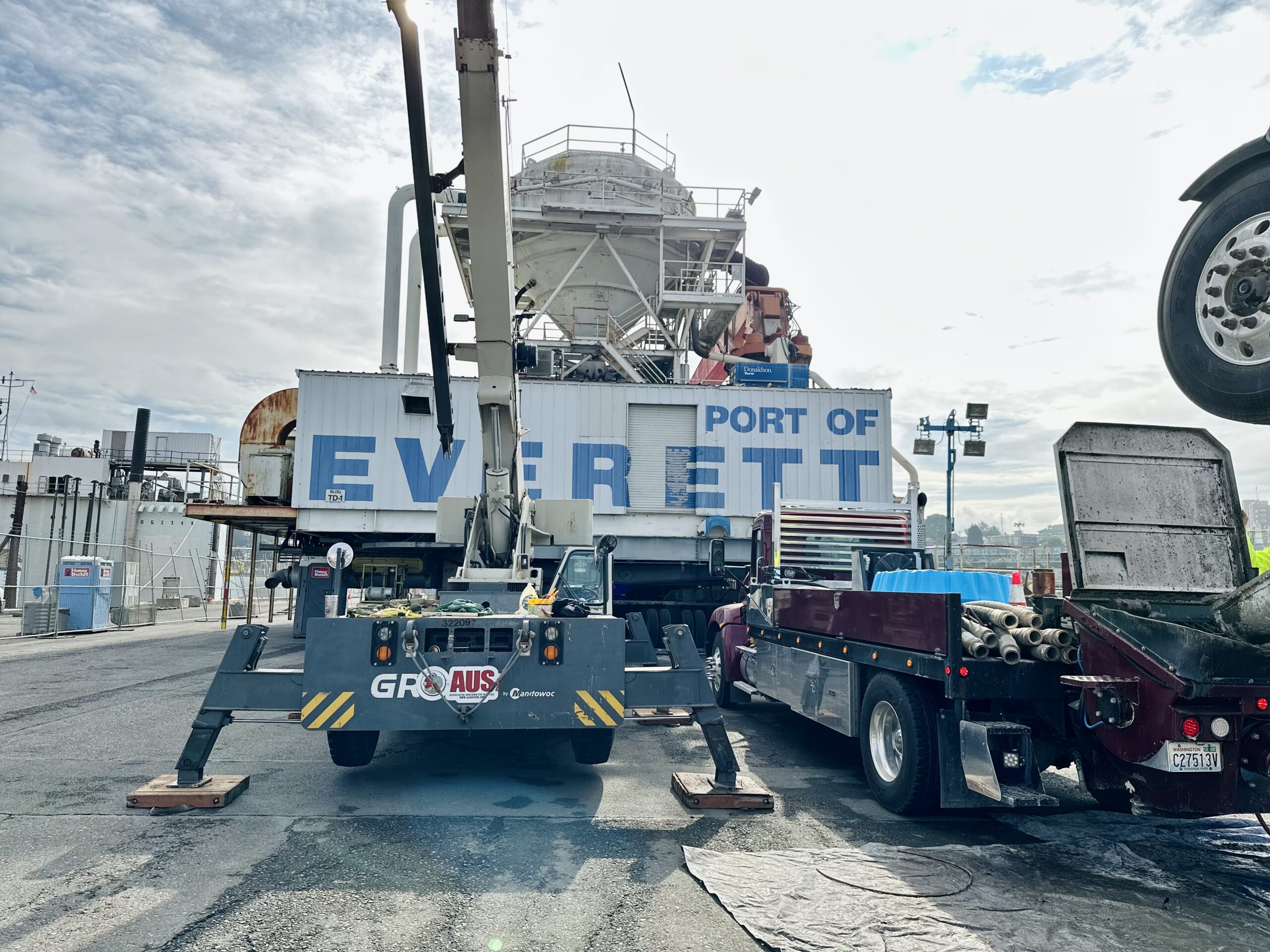
A 350-ton Grove hydraulic truck crane was set up on outriggers at the assembly site, where it could unload the unit segments from the shipping trucks, set the segments together for welding, and with its long reach, pick up completed units and set them on the Flexifloat barges.
Erection Scheme
Gerwick engineers felt that assembling the first 86ft, or 11 units, together vertically, then lowering them, tipping them and setting them in one piece against the dam would yield many advantages, if it could be done. Bolting would be superior, as the alignment of the unit back flanges would be in one straight line, and the seal installation (as well as the quality assurance) would be superior.
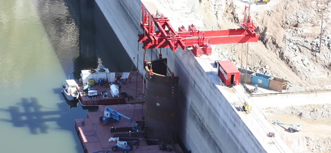
From the onset of the job, the concept of lowering the cofferdam to its final position against the dam would require a large crane on a barge, or a crane on top of the dam. The top of the dam position would be more stable, but since the top of dam was only 12-foot- wide, it would be difficult to fit and place a high capacity crawler of truck crane on such a narrow spot. A different piece of lifting equipment was needed, and Barnard asked several heavy lift contractors to quote on supplying equip- ment that could lift the 200+ tons of cofferdam off the barge, tilt the cofferdam to match the sloping dam face, and slide the assembly tight to the dam. Barnhart had suitable equipment and was selected for the job.
Two large beams fixed to the top of the dam were provided by Barnhart as support for two sliding beams and jacks to lift and position the cofferdam. The sliding jack beams could move out over the barges, and with four jacks, pick up the cofferdam, then lower it vertically to its final elevation. Then by lifting the front of the cofferdam and lowering the rear, the entire assembly was tipped to match the dam slope. The final step of the operation was to slide the assembly back against the dam. For this step, four 450-ton capacity stand jacks were used, which could easily handle the 200-ton cofferdam assembly. These jacks were positioned over four lifting points on the outside of the cofferdam shell on Unit 6. After the cofferdam was moved against the dam, the next operation was to core drill two-inch diameter holes for the 108 two-foot-long stainless steel anchor bolts that would provide vertical support for the cofferdam. The bolts were installed by the divers using hydraulic powered core drills with magnetic bases for easy and accurate positioning. The nuts were tightened with hydraulic impact wrenches and, with the help from dewatering pumps, the cofferdam seal space was compressed to an inch or less. Following the bolting of Units 1 to 11 to the dam, the remaining Units 12, 13, and 14 were floated under the strand jack and were lifted and set in place on top of Unit 11. The last 24 anchor bolts were then installed to complete the bolting.
The divers then placed grout in the center seal space, starting at the bottom of the cofferdam working their way to the top of Unit 14. This operation completed the sealing on the sides and bottom of assembly, and the cofferdam was now ready to be dewatered.
Barnard placed a dewatering pump in the bottom unit and was able to dewater the entire assembly in about one day. The specified maximum allowable leakage was 10 gallons per minute once the cofferdam was fully dewa- tered. The actual leakage was less than this rate and Barnard was able to maintain a dry cofferdam with nothing more than a small sump pump. Even during a 7.2 magnitude earthquake on April 4, 2010, with an epicentre about 100 miles from the dam, no problems were reported.
While the cofferdam was being set, the tunnel subcon- tractor, FoxFire Construc- tors, Inc. (FoxFire) of San Clemente, CA, was busy boring into the dam from the downstream side of the structure. Within a short time, FoxFire was able to bore through into a com- pletely dry space inside of the cofferdam as planned. FoxFire completed the pipe installation through the dam, placed concrete around the pipe, and then installed a bulkhead over the outlet in preparation for the future placement of the sliding gate valve. Phase 1 work was completed at the end of April 2010. For the next phase, the next Contractor will remove the cofferdam as part of the Dam Raise Project after replacing the temporary bulkhead with the permanent sliding gate.
Throughout the process of designing this complex cofferdam, our engineers delivered innovative design and installation solutions that solved the many challenges faced on this project. Our expert construction technical support and timely calcula- tions ensured the successful completion of this vital
structure that San Diego residents rely on to deliver a continuous and reliable source of water to their homes and businesses. We took great pride in providing the Water Authority safe and efficient designs for the San Vincente Low Level Outlet Cofferdam and enjoyed the opportunity to work with all the technical experts involved on the project.